

By Garrett Seeley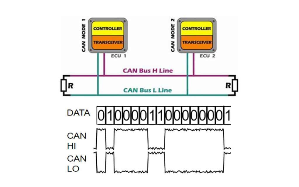
Imagine my surprise when I first discovered that there are several different networks in use in a modern MRI scanner. In fact, when studying at my most recent OEM school, I found several different types of networks used in the same device. It was a regular throwback to my college days. Academically, there were three principal networks topologies: a star, a ring, and a bus.
Surprisingly, each is still used in modern imaging, just not as they were originally used.
The first network is the most common and, therefore, the one I will mention the least; that is the star network. It is the common ethernet that most are very familiar with.
The second most common design for networks that I find is a bus design. There was a time when bus networks were quite popular in computer networking, however the speed and scalability of a star network eclipsed the use of bus networks for computers. Regardless, it is always amazing how older network concepts get updated and adapt to newer systems. They are reborn and rebuilt with a new purpose. One such network is a Controller Area Network (CAN). I thought that bus technology would not be used in modern electronics, however it is becoming popular for small scale sensor networks in manufacturing, automotive and, yes, medical devices. The appeal of the CAN bus is an ease of wiring combined with less hardware. It excels where speed and bandwidth are not a concern.
For example, in automobiles, a CAN bus connects over four dozen different sensors to the processors on a modern vehicle. Consider that an MRI is also completely microprocessor operated and essentially has dozens of sensors itself. All these sensors must communicate in an electrically noisy, possibly wet, physically difficult environment where temperatures can reach extremes of hot and cold. The wiring needs to be rugged and fault tolerant, but the messages exchanged are often short lines of text. The network requires fault tolerance more than speed and this is where CAN really stands out. CAN uses a two-wire, twisted pair as a communication backbone where all the devices, called nodes, connect to the main cabling, called the bus.
Each node connects in parallel wiring to the bus. All nodes can communicate to each other on the same bus in a broadcast format where all nodes hear the same communication. To transmit, a node waits for the line to clear, and then higher assigned priority node communicate or pass in order of priority. The communication then moves to the next in priority node. This may seem inefficient, but it ensures the most critical information is transmitted first.
In CAN, both wires, simply called CAN-High and CAN-Low, are used to send the communication bits by setting voltages in a mid-range as a default, for example 2VDC. To represent a change in the bit, both wires change, CAN-High goes high, and CAN-Low goes low. This represents a zero bit. To represent a 1 bit, both lines return to the base of 2VDC. In this way, only the difference or the similarity of the voltages per clock pulse is measured as a bit by all nodes. It is this difference or not that represents the 1’s and 0’s. That is important because it gives a natural fault tolerance. If there is a spike or electrical noise, the noise is experienced on both cables in the twisted pair. This minimizes differences caused by noise, therefore canceling the interference. Differences or no differences is basically how CAN works. The protocol includes some redundancy checks, a standard frequency, and a fixed frame bit length and then CAN becomes a small scale, noise tolerant ISO communicational standard.
A load resistor on each end of the bus ensures there are no reflected signals at the wire ends and that is all the network requires to work: nodes in parallel and end terminators. That’s it. Because this communication only needs 2 wires, CAN is generally used on a thicker conductor, offering more physical durability, hence the popularity in automotive and industrial applications. Additionally, CAN design may be changed, using a transceiver, to an optical cable. This allows for the straightforward design to have a great distance between nodes. I was quite surprised to learn about CAN as a communication technique for the sensors in an MRI. This is because the sensors do not require a lot of bandwidth, CAN represents an ideal small-scale bus for communicating to multiple sensors in a imaging device. As I started to keep an eye out for it, I noticed CAN used in other high-end scanners as well, not just in MRI applications. It seems to be common in larger medical equipment as a low priority sensor network.
This is not necessarily what a trainee can expect to find in all high-end imaging scanners, but it is common enough that elements of it will be used in multiple devices. CAN is a niche network design, preferable in small sensor networks for strings of simple devices doing small tasks. However, that statement describes a lot of designs of HTM devices. As technology grows and costs lower, we are going to find more and more sensors operating as standalone processing units reporting over a network and less as a thermocouple passing a voltage to a logic circuit. As that happens, bus networks like CAN will become more and more common.