

Sponsored by Innovatus Imaging

By Ted Lucidi, CBET
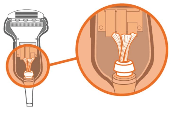
We’re going to continue in our series focusing on the key components within an ultrasound probe. This month, we’ll examine the wiring harness and cable jacket.
 After the acoustic array, the most failed component on an ultrasound probe is the wiring harness or system cable. After all, the cable is flexed hundreds of thousands of times during a probe’s life cycle. It is also subjected to accidental pulls, roll-overs and pinches. Wiring failures are something with which most of us are familiar, they are not just limited to ultrasound probes. Knowing this, one might suggest that OEMs develop wireless ultrasound probes. Well, they have. But, wireless probes have their own challenges. They can be easily dropped, hindered by excessive RF interference, experience poor signal-to-noise, and range/distance limitations. And, yes, they have even been lost or discarded into the trash bin. It will be sometime before wireless ultrasound probes become mainstream.
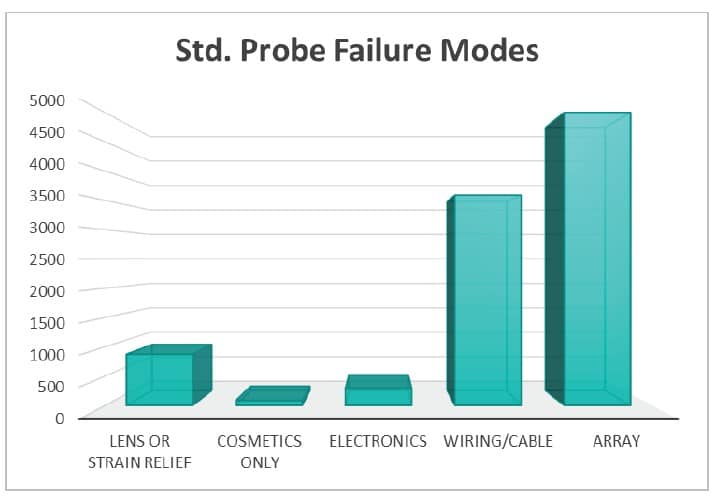
The graph shows about 2-years of data only including standard probes (omitting TEE and mechanical 3D/4D probes). Spanning just under 10,000 standard probe repairs, over 50% presented with array failures, while about 37% presented with wiring or cable failures. Failures to ONLY the lens, the strain relief, cosmetics, and electronics consumed only 13%.
Design
In legacy probe models, and even in some of today’s more-simple designs, the wiring harness may contain less than 100 micro-coaxial wires. That’s right, ONLY less than 100. Today’s more-complex probe designs have wire counts of up to almost 200. Traditionally, the purpose of the wiring harness was to carry the transmit and receive signals to and from the scanner/probe, and for most, it still is. Typically, there was one micro-coaxial wire for every acoustic element in the array.
More complex probe models, such as the Philips VL13-5, L12-5 50mm, and L18-5 increase the element counts in the acoustic array to 192, 256, and 288 respectively, yet still use a wiring harness containing about 170 wires. In these models, both the scanner and the probe electronics use multiplexers. The harness carries, not only the T/R signals, but also power and signals to control the Mux’s. Newer live-3D volumetric probe models, such as the Philips X5-1c and GE 4Vc-D have over 3,000 acoustic array elements, yet still only use a harness with less than 200 wires.
Common Failures
Barring physical damage, when the cable is cut, pinched, rolled over, or pulled, wiring failures occur as a normal part of almost every probe’s life cycle. Wiring failures usually lead to service calls being placed for non-descript problems or general terms, such as noise artifacts. Depending upon the level of detail provided by the customer, wiring failures may be challenging to reproduce in the field without a consistent test process. Our transducer assessment guide provides step-by-step instructions on a consistent testing process. More information about the guide is below.
Most wiring failures begin to present as intermittent, vertical streaks of color in color Doppler mode or as intermittent static or sharp “crackling” sounds in CW Doppler mode. As the wires continue to degrade, intermittent black, vertical, lines of dropout may appear in 2D mode. For probe models, such as the L12-5 mentioned above, if one or more of the wires that are used for control or power to the Mux’s fails, users may be presented with a double image or partial image. Sometimes, on more advanced probe models, only an error code is displayed.
Typical Solutions
There are multiple methods that service providers use to address wiring intermittencies.
- One frequently used approach is to cut-back and re-terminate one end of the wiring harness … attempting to remove the intermittent section of wires. The challenge with this approach is that the system cable becomes shorter and shorter with each repair attempt. Most times, sonographers and end-users notice the shorter cable and are less than satisfied.
- Another solution is to harvest used cables from other defective probes. The difficulty with this solution is that you don’t truly know what you’re getting. A cable is designed to only flex x-number of times before degrading. How worn is the cable on your last exchanged probe? The supplier is betting that the life cycle of their cable will be longer than their warranty period. Is that something you’re willing to risk?
- One, final, ‘typical” solution is to replace your probe’s OEM cable with a generic, one-size-fits-all, replacement cable from an overseas supplier. Although this solution may get your probe working again, it bypasses the design controls of the OEM. Performance, safety and efficacy might become compromised.
Innovatus Preferred Solution
The ideal solution to address any cable intermittency is to replace the cable with a new one. The challenge is that OEMs do not sell replacement parts for ultrasound probes to ANY independent service provider. The next-best solution would be to fabricate a replacement cable proven to be OEM-equivalent. It’s not an easy task. Most of the wires are classified as micro-coaxial, and can be as fine as 48-guage (thinner than a human hair). GE’s 4Vc-D utilizes 52-gauge wires. They are the finest that we’ve seen in ultrasound probe designs. Items to be considered when designing a wiring solution in an ultrasound probe are the length, outside diameter, inside diameter, jacket material, dielectric type, solid or stranded core, magnetic permeability, shielded or unshielded, capacitance, inductance, and resistance.
As an FDA-registered manufacturer of ultrasound probes, Innovatus has unparalleled expertise to test, classify, and design an entire cable harness. We currently fabricate over 100 unique cable assemblies. Each solution is verified and validated against the OEM intended design. We continue to repair probes for several OEMs based upon our deep understanding of the full device and track-record for sustainable results. As a result, we are able to deliver sustainable repairs and performance that can renew the product’s life cycle at a fraction of the cost of exchanging the probe.
For more information on this topic, or to request our transducer assessment guide, reach out to training@innovatusimaging.com