

Sponsored by Innovatus Imaging

By Ted Lucidi, CBET
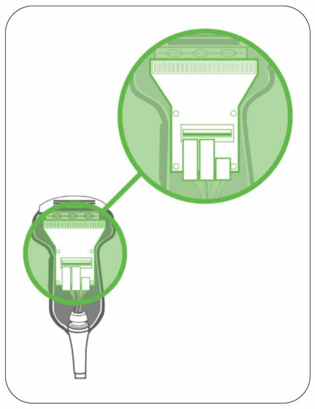
We’re going to continue in our series focusing on the key components within an ultrasound probe. We began with the acoustic lens and moved to the acoustic array. This month, we’ll examine the scan head electronics.
The scan head electronics may be some of the most overlooked components within an ultrasound probe. After all they are rarely seen unless the probe has sustained some significant physical damage. As demands for enhanced image quality, 3D volumetric imaging, and improved ergonomics have increased, so has the complexity of the scan head electronics. Failures to this component are not as common as array damage or cable damage, yet they occur.
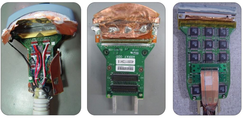
 In legacy probe models, and even some of today’s more-simple designs, the scanhead electronics were merely a bridge between the acoustic array and the wiring harness. Today’s more complex designs employ some very advanced electronics such as multiplexers. One reason is that some probe designs utilize more acoustic elements in the array than there are wires in the cable harness or transmit/receive channels in the system. Other more-complex designs e0xist in probes used on Butterfly systems and other handheld or wireless systems. In these designs, the entire ultrasound hardware may be housed within the probe itself.
Mechanical 3D volumetric probes add an additional layer of complexity. Not only is the top-half of the probe filled with oil, but there’s also a motor and associated electro-mechanics contained within the handle. If, or when, the oil bladder or transducer dome leaks or perforates, oil exposure can add another level of complexity to your probe failure.
With live 3D volumetric probes, such as the Philips X5-1c and X8-2t, and the GE 4Vc-D and 6VT-D, much of the beamforming, traditionally performed in the scanner console’s front-end, is performed by the scan head electronics. In these, highly advanced designs, the acoustic array is bonded to and controlled by an ASIC (Application Specific Integrated Circuit). An array with up to 9,000 acoustic elements is being driven by a cable having less than 200 micro-coaxial wires and even less transmit/receive channels in the scanner (typically 64-128).
Common Failures
We can say, with confidence, that most of the damage and failures to the scan head electronics have been a result of contamination, oxidation, and corrosion to the electronic components and physical connections to the PCBs. We’re often asked, “How does this occur?” In many cases, the seams joining the two halves of the probe housings have degraded and are no longer fluid proof. In other scenarios, the seal surrounding the acoustic lens has degraded and enables scan gel, chemical disinfectants, and other contaminants to gain access to the sensitive electronics. Once a seal is compromised, every subsequent use, cleaning, and disinfection can result in contaminants entering the probe.
 In the past, most general-use, or standard, ultrasound probes were merely cleaned between each use. Excess gel was removed and, maybe, the probe was wiped with a soft washcloth moistened with a mild cleaner. More recently, standard probes are being not only cleaned with harsh intermediate-level disinfectants, but some sites high-level disinfect ALL probes via a heated and vaporized hydrogen peroxide system (Trophon, Ethos, etc.). Traditionally, only endo-cavity and TEE probes were high-level disinfected.
The materials used in today’s high-tech ultrasound probes have been enhanced to allow for increased exposure to harsher chemicals. The challenge is, although a specific chemical may be approved for use on a specific probe model, compatibility does not address the long-term effects of exposure or over-exposure. Approval typically only attests to the chemical NOT inducing more acute or short-term effects. An interesting note … multiple OEMs have recently added statements to their manuals instructing users to rinse probes of residual chemicals following disinfection. In our experience, this is not standard practice and could be considered a contributor to premature wear and subsequent probe failures.
Common Symptoms
Failures to the scan head electronics can result in a wide range of failures. Sonographers may report problems such as no image whatsoever, double images, missing information in the image, noise artifacts, lightning bolts in the image, and Doppler artifacts. With more advanced probe designs, such as the Philips X5-1c, X8-2t, or GE 6VT-D, error codes may be displayed on the scanner console.
Most times, damage to the scan head electronics is addressable through repair though challenges may exist within today’s most-advanced 3D probes. The image below shows the microscopic wire connections to the array within the Philips X8-2t. A healthy array is on the left. An array which has had multiple connections vaporized via short circuits due to fluid invasion is on the right. Note the tip of a ballpoint pen in-between for scale.
How to prevent
The cost of addressing a worn/degraded seam or seal may be several hundred dollars versus thousands to address a performance problem. As such, the most-effective means for preventing costly failures is through routine visual inspections. We’ve created a visual inspection guide designed to be shared with staff members and even posted in each scan room and sterilization department.
We suggest partnering with your sonographers. Ask for 15-minutes within one of their department meetings. Discuss the importance of frequent, thorough, visual inspections. Share the visual inspection guide. Present the opportunity of a single person visually inspecting EACH probe EVERY week. Each week, a different staff member would perform the inspections. If there would be any item of concern, the HTM team would be notified, and the probe would be sent out for a cost-effective repair.
For more information on this topic, or to request our visual inspection guide, reach out to training@innovatusimaging.com