

Sponsored by Innovatus Imaging

By Ted Lucidi

Today, we’re surrounded by countless pieces of electronic technology. Who doesn’t have a cellphone in their pocket, or near themselves, somewhere? We even wear our technology. Almost every electronic device contains some type of oscillator circuit, which has the potential to affect the electro-magnetic spectrum. Whether you call it Electro-Magnetic Interference (EMI), Radio-Frequency Interference (RFI), or environmental/atmospheric noise, EMI is a disturbance, from an external source, which affects the performance of an electronic circuit. Multiple articles have been published by the World Health Organization and the National Institutes of Health describing the overabundance of EMI as electronic pollution. They cite, “In many cases electronic pollution is much stronger than any natural sources of radiation.”
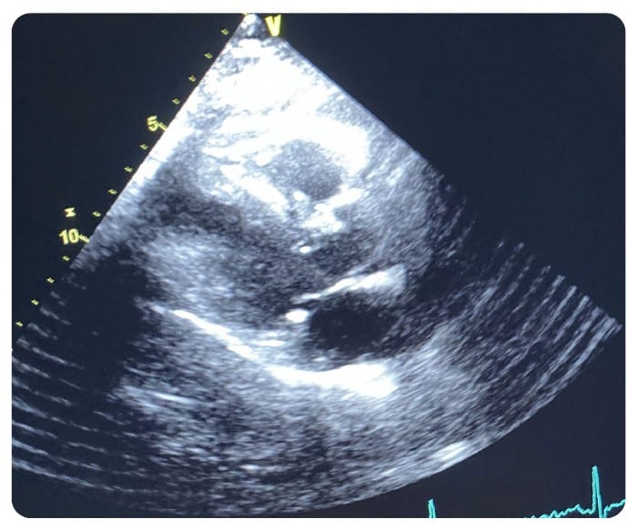
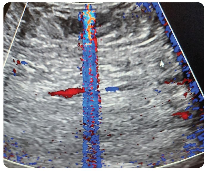
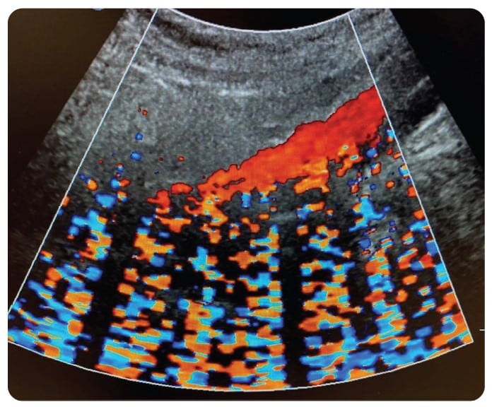
With the proliferation of IoT and wireless technology, the health care setting is even more densely saturated with electronic pollution. Throughout my 30-plus year career in ultrasound, one of the most frequent and most challenging problems to solve has been related to noise artifacts being displayed in an ultrasound image. Typically, these present as axial bands of constant or flashing color in Color Doppler mode. Intense sources of noise can affect 2D imaging in the form of faint gray, semi-axial streaks and/or semi-circular swirls overlaid on the image.
Health care facilities are filled with massive amounts of RF pollution. At the macro-level, X-ray generators, electro-surgical generators, walkie-talkies and countless wireless devices quickly come to mind. I can confidently say that there are hundreds more that never would. Microwave ovens, florescent light ballasts, surgical lights, gel warmers, motorized doors, elevator motors, treadmills and, yes, a land-line phone are some of the more obscure sources that have, in-fact, been the root causes of noise in 2D and Color Doppler Modes. In the case of the elevator motor, successful troubleshooting took three months (late night visit – audible sound as elevator car was passing the floor I was on).
Manufacturers design their ultrasound consoles and probes using various technologies to limit susceptibility to internal and external sources of RF energy. The concept of shielding is not new by any means and is credited to Michael Faraday in 1836. The main purpose is to prevent EMI from impacting sensitive electronics. In concept, successful shielding is achieved by using a metallic screen, or Faraday cage, to absorb EMI in the vicinity of the device. The shield absorbs EMI signals and funnels them to a ground connection or a virtual ground plane. By absorbing EMI signals before they reach the sensitive circuitry, the protected signals are kept clean.
Most modern ultrasound consoles and probes are designed for increased EMI suppression. Still, there is no console or probe that is totally impervious to strong sources of RF energy. The amount of suppression depends on the types of technology used, the amount (or volume) of shielding and material used. Each affects the range of, the strength of, and the frequencies that can be absorbed by the shielding.
Probe Design
As an FDA-registered manufacturer of ultrasound probes and ultrasound-related devices, Innovatus Imaging has a complete understanding of the technology, and following are some common techniques for shielding used in probe design. Not all probe models are fully shielded and there are varying degrees of shielding based on the intended design of the final product.
Starting at the scanhead, the array and scanhead electronics are wrapped in a copper foil. Each wire within the wiring harness is a micro-coaxial cable, meaning that each individual wire is individually shielded, and the entire harness bundle is typically housed within a wire braid. One end of the wire braid is soldered to the foil, which surrounds the scanhead electronics, and the other end is secured to either 1) the metal connector housing or 2) a section of the connector electronics which comes in contact with a grounded area within the console, when connected. Ideally, the entire probe from the array to the connector electronics would be surrounded by a metal Faraday cage and would be connected to the console’s ground plane.
Console Design
Console technology ranges from full-size systems to hand-held devices and the need for and level of shielding, again, varies based on the intended design. Most of today’s full-size consoles are modular designs, meaning that the power supplies, front-end processor (card cage), back-end processor (typically a PC) and all accessories are separate independent devices, merely assembled into a common frame. The quality of the physical connections, of all the interconnected components, to the chassis can influence the effectiveness of the shielding. Most, or all, of the external connections to the scanner (external video, network, USB, etc.) including the probe connections are tied to some type of ground plane which, ultimately, are tied to the system/earth ground.
Potential Shielding Faults
Items such as network cables, external video cables, USB cables, loosely connected or disconnected from the wall or other device may serve as antennas.
Excessive dust within the card cage(s), power supplies and console, as a whole, may serve as a bridge for EMI to bypass shielding.
Oxidation on spring clips on card cage covers and surrounding probe connector ports may impact the quality of shielding between devices and ground.
The power cord resistance and ground (varies depending on how many times the cord has been run over or pulled), the quality of the console’s connection to the facility’s ground system (receptacle quality) and ultimate connection to earth ground may affect EMI suppression.
Big Picture
For maximum RF suppression, there needs to be a solid, quality connection between all shielded components, accessories, probes and cables from end-to-end. Any compromise in the direct connection to the grounding system may cause the console and/or the probes to become more susceptible to internal and/or external EMI. After 30-plus years supporting diagnostic ultrasound, my colleagues and I have some great examples of troubleshooting noise artifacts that will make your head spin. Next month, we’ll share some strange, but very true, scenarios and provide a strong framework for troubleshooting.
Ted Lucidi, CBET, is the director of commercial operations and business analytics at Innovatus Imaging.
